This Mobile Sensor Platform (MSP) includes several minor modification of the 2nd gernation of MSPs. All of the MSPs carry devices which enable imaging, distancing, and wireless communication functions. The Image processing algorithms help the mobile sensor understand its environment. A group of these sensors can be coordinated to better react to or reason about real-world phenomena. Most of the existing sensor network testbeds are fixed. The few mobile testbeds either have limited processing capability that prevents them from running interesting and practical applications like target tracking, sensor deployment, and other mission-oriented tasks; or that they are too costly for group deployment. AICIP group will design and implement a mobile sensor network testbed that can provide sufficient processing capability for both 1-D signal processing and 2-D image processing at low cost (<$500 each platform).
Wheel and Axle Must Turn as One...
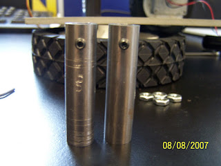

In the photos above, you see the scratches made by the wheel's set screw on the drive shaft extension rod. Again, I am sure this occurs due to both the set screw and the extension rod's round shapes. Two round pieces will threfore not maintain enough contact force necessary to keep the wheel and axle moving together as one.
After showing this to Ragul, it apears there were supposed to be holes drilled into the drive shaft extension rod large enough to allow the set screw to become seated just inside the rod. Those holes are not present. Ragul and Austin are going to look into this....
After that we should be ready to roll...


3 comments:
I bought a couple of wheel collars to use to hold the wheel on the extesion shaft.
Results: The wheel stayed on the shaft but the wheel did not move at the same angular rate as the shaft.
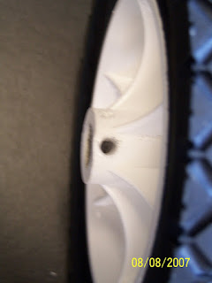
I'm now thinking a tension pin could be inserted both through an existing hole in the wheel hub and a drilled hole in the extension shaft.
Subject: RE: Wheel and Axle must turn as one... update
Austin, thanks for your reply. I'm looking forward to working with you this fall to get this done finally.
My personal goal is to get some solid experience building the MSP then get some experience observing how the different MSP algorithims work.
That being said, I'm going to respond to your questions below in Bold so that my comments are obvious.
I can sum up my answers with the following:
After reading your comments, I agree with you that my expectation of the degree to which the MSP must be rigid may be too high for the actual enviroment (lab floor, or parking lot asphalt or side walk pavement) that has to work in is more forgiving.
My rought test of how well the wheel mated to the axle consisted of simulating motor tourqe with my hand on the wheel. The big assumption here was that my torque would be equal to or greater to that provided by the motor. My thought was that if the wheel and axle(connection between wheel set screw and axle) could rotate as one under the stress provided by my hand then we had a great connection between wheel and axle.
Without seeing the MSP move on the floor I can't get a good "feel" of how much torque the notor exterts on the wheel's set screw. So there is great value at least for me to see the motor in action on a set of wheels as the MSP moves accross the lab floor.
Paul,
The what are you doing to cause the wheel to spin on the shaft? You have the
motor "end" of the shaft positioned so that the set screw on that tightens
down to the flat spot the actual motor shaft right?
Yes, I have the set screw on the flat side of the motor shaft.
Oh, I notice one key detail that is wrong about the way your attaching the
wheel. The side of the wheel rim/hub (the white plastic part) that has the
wheel's set screw in it faces out (does not face the motor).
I tried both sides with no difference in results (set screw facing in and out)
Also, Raghul is
correct in that the first pair of shafts have a "dip" drilled at the ends for
the wheel's set screw to seat in.
I noticed the same...the last four out of the five pairs of shaft extension don't have dips drilled into them.
This is "easily" fixed. < "Famous Last Words")
I think your over estimating the ability of the robot to create a situation
where the wheel slips on the shaft. This robot can not operate in rough
terrain. It can only operate on basically flat terrain, so the lab floors,
the floors in Ferris, side walks that don't have more than 1/4~1/2-inch
"bumps", wheelchair ramps, etc.
You're absolutely right here... I see that now...
Your expectations for the rigidity of the motor, shaft, wheel connections
exceeds the mobility capabilities of the robot/MSP. Also the plastic of the
wheel hub was not manufactured with our application in mind, so your expecting
to much of it as well. If your not careful you will create an even bigger
issue which is that the threaded hole for the set screw in the wheel hub
(white plastic part) can very easily be stripped and enlarged to the point
were the set screw no longer has anything to grip. I noticed that this hole
on the wheel you've been testing with looks like its being enlarged.
Yes, I know this issue well... I've stripped the holes in Two Wheels..
These wheels will have to be replaced. I also see the tourqe necessary to
tighten this set screw is minimal.
Don't get me wrong, your concern is very much merited, but you have to keep in
mind the environment in which the MSPs are going to (capable of) operate in. I
have noticed the weakness in the wheel's hub, but my concern is more in the
that the threaded hole the wheel's set screw is in will strip. Also you can
over tighten the wheel's set screw very easily. When it is over-tight the set
screw is pushing the white plastic hub away from the metal shaft and you can
actually see the gap when looking straight a hub. This could cause the actual
plastic of the hub to crack where the set screw is passes through it.
I do have the robot with the first pair of the shafts with me.
Talk to/see you later.
Austin
-----Original Message-----
From: Gunasekaran, Raghul [mailto:rgunasek@utk.edu]
Sent: Thu 8/9/2007 1:54 PM
To: Donnelly, Paul William
Cc: Albright, Austin P.; hqi@utk.edu
Subject: RE: Wheel and Axle must turn as one... update
Hi All,
For connecting the motor to the wheel, we have a metal connector. I believe
the first pair of connectors(Paul didnt get to see that) we did and it worked,
we then made another 4 pairs. On the first pair we made, the metal connector
has a hollow opening on side, which slides onto the motor shaft and we have a
set screw which hold this tight, this is perfect and we do have the same on
the other 4 pairs.
For connecting the wheel to the metal connector, a set screw was drilled
through the plastic on the wheel and then locks on to the metal connector, on
the metal connector their is a small grove for the set screw to lock on. I
believe this was done on the first pair(Austin, I think you have the first
pair we made, I dont see it in the lab, correct me if this is not the setup on
the metal connector.).
This small grove, was not made on the rest of the four pairs, which is
basically what Paul is trying to point out, the fact that the set screw tip
which is flat sits on the smooth cylindrical metal connector surface. In Pauls
view, this is no good contact and the motor wheel connection would slip,
meaning the motor would rotate but the wheel wouldn't.
(Lengthy mail summary) if this is the case then we need to make small grooves
or incisions on the metal connector.
Regards
Raghul
-----Original Message-----
From: Donnelly, Paul William
Sent: Thu 8/9/2007 10:33 AM
To: Hairong Qi; Gunasekaran, Raghul; albrightap@ornl.gov
Cc: Donnelly, Paul William
Subject: Wheel and Axle must turn as one... update
Hey I spent some more time and took another look at this problem. I also had a
chat with Ragul about it as well.
The problem is that the MSP's wheels can not form a solid lock with the drive
shaft extension rod. It looks like the rod should have had a hole drilled in
it big enough for a set screw to imbed itself into the rod. Maybe this hole
should be threaded so that the set screw locks into place. Take a look at the
photo's here: http://msp-log.blogspot.com/
Another solution would be to drill a small hole through the rod so that a long
tension pin could fit through the wheel hub and extension rod permanantly.
This would ensure that the wheel and axle will continue to turn as one without
further adjustment. I'd recommend a 5/32" tension pin and 9/64" hole.
What do you think?
-Paul
-----Original Message-----
From: Donnelly, Paul William [mailto:pdonnell@utk.edu]
Sent: Thu 8/9/2007 10:33 AM
To: Hairong Qi; Gunasekaran, Raghul; Albright, Austin P.
Cc: Donnelly, Paul William
Subject: Wheel and Axle must turn as one... update
Hey I spent some more time and took another look at this problem. I also had a
chat with Ragul about it as well.
The problem is that the MSP's wheels can not form a solid lock with the drive
shaft extension rod. It looks like the rod should have had a hole drilled in
it big enough for a set screw to imbed itself into the rod. Maybe this hole
should be threaded so that the set screw locks into place. Take a look at the
photo's here: http://msp-log.blogspot.com/
Another solution would be to drill a small hole through the rod so that a long
tension pin could fit through the wheel hub and extension rod permanantly.
This would ensure that the wheel and axle will continue to turn as one without
further adjustment. I'd recommend a 5/32" tension pin and 9/64" hole.
What do you think?
-Paul
I later replaced my hand as the torque input with the a 12V battery. This allowed me to determine very quickly if the set screw was suffciently tightened downward onto the axle.
The result of this test also convinced me that a groove drilled into the axle would greatly improved the connection between the set screw and axle.
Post a Comment