This Mobile Sensor Platform (MSP) includes several minor modification of the 2nd gernation of MSPs. All of the MSPs carry devices which enable imaging, distancing, and wireless communication functions. The Image processing algorithms help the mobile sensor understand its environment. A group of these sensors can be coordinated to better react to or reason about real-world phenomena. Most of the existing sensor network testbeds are fixed. The few mobile testbeds either have limited processing capability that prevents them from running interesting and practical applications like target tracking, sensor deployment, and other mission-oriented tasks; or that they are too costly for group deployment. AICIP group will design and implement a mobile sensor network testbed that can provide sufficient processing capability for both 1-D signal processing and 2-D image processing at low cost (<$500 each platform).
MSP Construction Photo Log
Tuesday, October 16, 2007
Motor Torque Test
I applied 12V to the right side motor to determine if the wheel hub (pictured on the outside of the wheel axle) would help the wheel and axle turn as one.
No go... The axle turned totally free without the wheel...
So after removing the hub and carefully tightening down the set screw both wheels and axles turn as one!!!
Well.. at least I have a definitive test now...
Monday, October 8, 2007
08 Oct 2007
.jpg)
I
This was a first attempt to make more progress and uncover obvious construction issues. (One step forward two steps back...What a tango this work is...
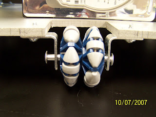
I've added the universal wheel and motherboard to the MSP. It looks like I'm going to have to move the motherboard back to make room for the camera.
I had to use pins instead of the hex screw as the axle for the wheel since the inner diameter of the L-brackets were smaller than than the outer diameter of hex screw. The length of pin is longer than expected and allows the wheel to move laterally-which may introduce path errors.
My next step is to install the battery, h-bridge and motor to begin testing the alignment of the vehicle as it moves in the x and y directions . I must figure out a way to program the TI Quad Half-H driver. This will be good practice since I'm currently enrolled in a Intro to Digtal Design class.
Monday, September 17, 2007
Thursday, August 9, 2007
Wheel and Axle Must Turn as One...
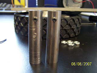
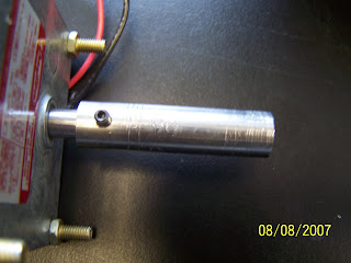
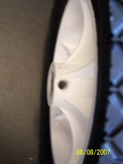
In the photos above, you see the scratches made by the wheel's set screw on the drive shaft extension rod. Again, I am sure this occurs due to both the set screw and the extension rod's round shapes. Two round pieces will threfore not maintain enough contact force necessary to keep the wheel and axle moving together as one.
After showing this to Ragul, it apears there were supposed to be holes drilled into the drive shaft extension rod large enough to allow the set screw to become seated just inside the rod. Those holes are not present. Ragul and Austin are going to look into this....
After that we should be ready to roll...
Tuesday, July 31, 2007
Mounting the Wheels: Tuesday July 31, 2007

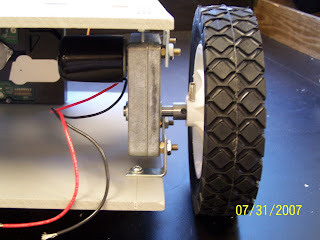
The # 6-32 1/2" screws were the best fit for the hard drive. The drive is now mounted on the vehicle. I've included washers and hex nuts to contribute to the rigidness of the chassis. That alone has increased the stability of the vehicle. One word of caution here, ensure that the support bolts and hex nuts are all torqued as evenly as possible. Without observing this precaution it is very possible to bend the entire chassis.
I ran into a slight problem while attaching the wheels to the drive shaft of the motor.
As is the standard, there is a set screw on the drive shaft extension. This extension secures it to actual drive shaft of the motor. The drive shaft has a flat spot which lends itself well to maintaining a firm friction contact with a set screw within the drive shaft extension.
The wheel also has set screw meant to lock down upon the opposite side of the drive shaft extension. Unfortunately in my case, the set screw was unable to maintain a good grip on the extension drive shaft-no matter how hard I torque down the set screw. The set screw actually spins freely within the plastic wheel axle which allows the wheel to freely spin independent of the drive shaft.
Observing old designs: It looks like they used a plastic sleeve inside the wheel axle and some sort of epoxy.
Friday, July 27, 2007
Construction of Platform
 So in this photo I've mounted the two motors and drive shafts for the rear wheels of the vehicle. -that was easy. However, as I tried to mount the hard-drive to the board using the pre-drilled holes as seen at the bottom of the photo I learned that the holes were spaced so as the IDE interface points to the viewers left. This is somewhat problematic since the IDE cables are to be fed through a hole that will be to the right of the hard drive. So the drive's IDE interface must point to the right for cable management purposes. This will be a minor fix. Using the fractional tape measure, the center hard drive support hole will have to be drilled 6.75 inches from the left side of the board. Another issue involves the depth of the mounting holes on the hard drive itself. I figured that 6-32 machine screws were the right width for the holes. However, I soon learned that the holes are not all drilled to the same depth. So the 6-32 3/4" were too long for two of the holes inside the hard drive. So I'm going to try 6-32 1/2" screws in the morning. I should have the platform completed in the morning and ready to receive the electronics.
Whoever decided to buy a fractional tape measure- Bless You!!! -Paul
Subscribe to:
Posts (Atom)
